


[toc]
Ultra-Light Floating Floor (ULFF )
A “Floating Floor” is a floor which is applied on top of an insulation with no solid connection to the super-structure of a ship, which means pipe penetrations, columns, foundations for machinery etc. must be disconnected from the floor system. The acoustic performance comes from the mass and spring concept, where the insulation is the spring and the top layer is the mass.
The Sikafloor® Marine Ultra-Light Floating Floor system comes in two different versions where the only difference is the type of insulation sheet used underneath the floating floor. Both versions have an A60 certificate when applied in a thickness of 50 mm or more and can both be applied including Sika’s special visco elastic solutions.
Brand-new Sikafloor® Marine Ultra-Light Floating Floor, based on highly sophisticated, reusable technology never seen in the marine business before.


More information on Sika homepage.
Weight saving potential – Floating Floors
In order to substantiate the above business case on weight savings, reduced fuel consumption and CO2-footprint, Sika has ordered an independent study from GSR Services on this data. The study compares two different Sikafloor® Marine floating floor systems when used in a large cruise ship newbuilt construction. GSR Services GmbH compared the Sikafloor® Marine Litosilo Steel, which has a total weight of 48.1 kg, to the Sikafloor Marine UL-FF 2.
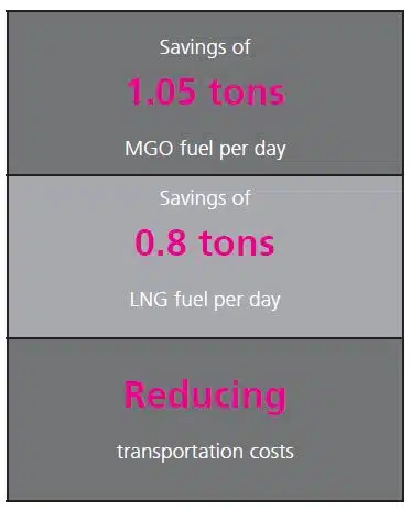
1. FUEL SAVINGS MGO (MARINE GAS OIL) (GSR STUDY)
Comparing the installed power with related fuel consumption per sailing day results in a daily MGO consumption of approximately 257 tons with the conventional floating floor system. With the new floating floor system UL FF-2, a reduction of 0.41% equals savings of approximately 1.05 to of MGO fuel per day (or 383 tons/year – depending on sailing days). With a view on MGO prices of 1.100 $/t at the time of data collection, this corresponds to a daily saving of 1.158 $ (up to 422.670$/year – depending on sailing days).
2. FUEL SAVINGS LNG (GSR STUDY)
The specific fuel consumption including operational pumps for one full sailing day results in a daily LNG-consumption of approximately 194, a reduction of 0.41% of installed power saves approx. 0.8 to of LNG per day (approx. 292 t/year – depending on sailing days).
With a view on LNG fuel prices of 3000$/t at the time of data collection1, this corresponds to a daily saving of 2.389 $ (up to 871.985$/year – depending on sailing days). It is to be noted that LNG bunkers are available in different qualities mirrored in ‘lower heating value’ which has been taken into consideration for the calculation.
1 www.shipandbunker.com, 05.08.2022
Raised floors and platforms
Thanks to their rigidity and their specific purely metal structure Metawell® panels are particularly well suited for the use in raised floors and platforms. There are several Metawell® panels that can be considered for floors applications. The choice of the panel type depends on the compressive strength that is requested in view of the point loads and on the maximum weight the total construction is allowed to have.
-

- Raised floor ship’s bridge

-

- Raised floor ship’s bridge shell

-

- Raised floor example

-

- Raised floor example 2

Limiting conditions:
- Compressive strength / floor covering
- Load assumption
- Grid distance of the sub-construction
- Support width of the panel
- Allowed deflection
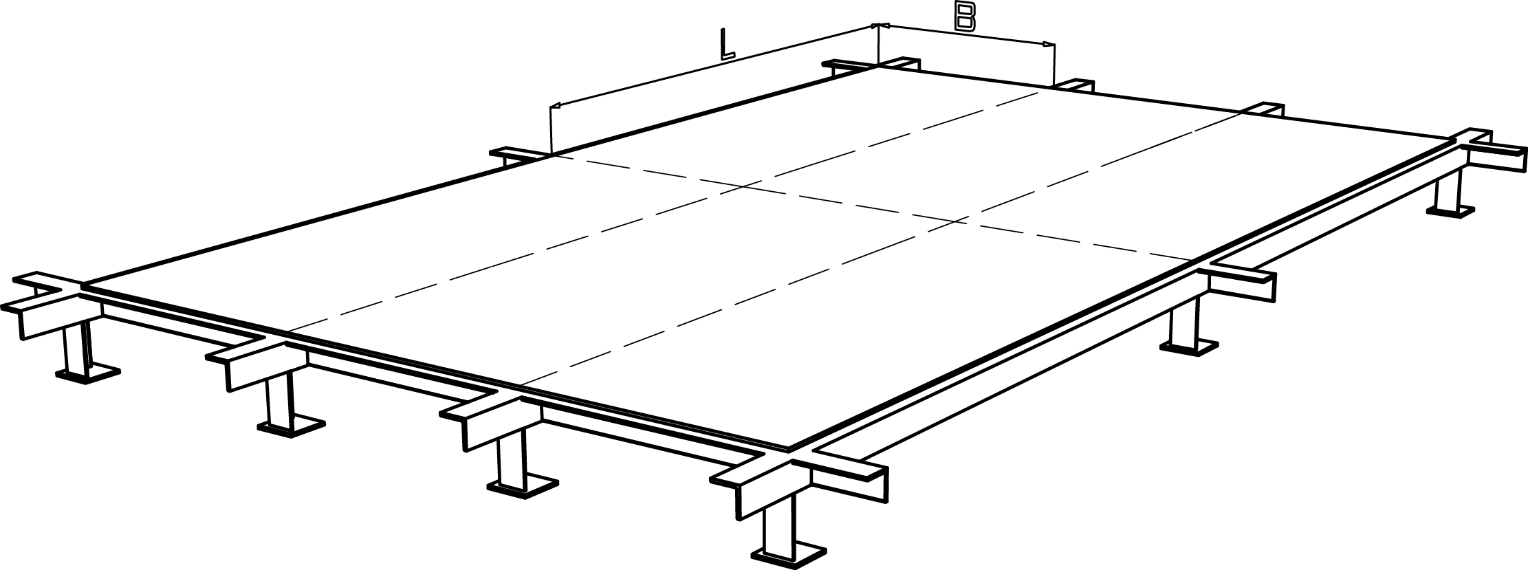
Grid width of the sub-construction
Compressive strength and rigidity
The compressive strength and the rigidity that are requested for floor panels is strongly dependent on the utilization itself and the individual floor covering.
Accordingly, the panel type Alu hl 10-03-10 hl / H11.5 is used for floor areas with correspondingly strong coverings (e.g. parquet) and panel type Alu hl 10-03-10 hl / H6 for floor areas with thin coverings (e.g. carpet).

Load assumptions
Floor panels are generally designed based on area loads. The standard loads assumed are 300 kg/m² and 500 kg/m².

Load case area load
But considering area loads alone is mostly not sufficient for practical use as the subjective feeling of the “user” is also very important. In order to get as close as possible to the real application, the point loads in the centre of the panels, which appear e.g. by walking on the panel, must not be neglected.

Load case point load
Point loads in the middle of the panel usually present the worst load case.
As basis for dimensioning calculations the following load cases are assumed:
- Area load 300 kg/m²
- Point load 100 kg in the centre
The panels‘ performance with other loads can be determined by calculation. The point load is not simulated as mere point load in the literal sense of the word but spread onto a circle with a diameter of 60 mm (“shoe contact area“). Superstructural parts and furniture should be fixed directly to the substructure in order to avoid point loads.
Grid distance of the substructure
The grid distance is dependent on the maximum deflection, the allowed bending moment and the condition of the total construction. Preferably the most economic use of the chosen panels (favourable formats to avoid scraps) should be taken into account, too. Therefore the subsequent examples are based on panel widths that can be produced out of Metawell® panels with as little waste as possible. Of course, rectangular grids can be used as well.
Support of the panels
It is only theoretically possible to fix a floor panel absolutely firmly (see case ‘a’).
Even when the panels are screwed to the substructure, there is some rotation movement.
For any further study it therefore seems more reasonable to take case ‘b’ as a model in order to have the requested safety regarding the deflection. If a panel covers several fields, the deflection is about 10 to 20 % less.
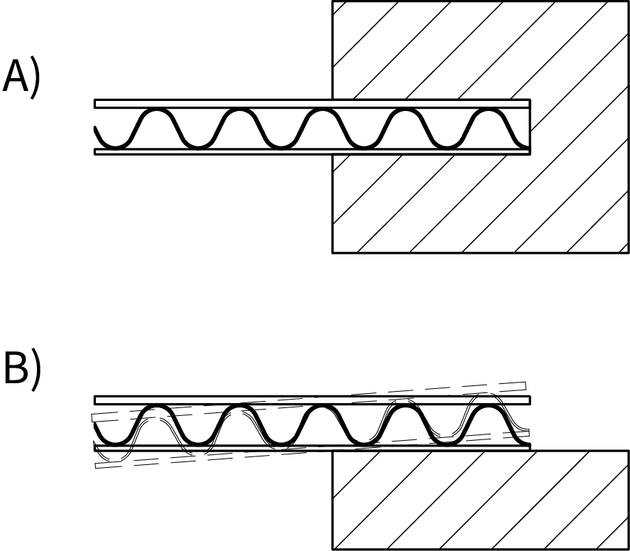
Support of the panels case a): panel firmly fixed, no twisting case b:) panel loosely supported, rotating
Limits for the deflection
Floor panels are usually dimensioned respecting the following limits:
- Deflection < 0.5 % of the smallest edge length (L/200) or
- Deflection < 1.5 mm
The smaller of the above values should be assumed as maximum deflection allowed so that the yielding of the panel is not felt by those who walk on it.
Design expamples
The following design examples refer to the two standard cases:
- Floor with area load of 300 kg/m²
- Floor with area load of 500 kg/m²
Since the loads enter linearly into the deflection of the panels it is no problem to project the deflection with other loads than those shown in the diagrams. Should different grid distances be used, it is recommended to consult the manufacturer beforehand. The subsequently described applications assume a twistable support as this case is nearer to reality than the non-twistable support. The thus determined deflections are therefore safe. They do not contain any further safety factor.
Design example 1
Given conditions for a raised stage floor with carpet:
- Load: surface load 300 kg/m²
- Flooring: carpet (approx. 6 mm)
- Grid width: 500 x 1000 mm
- Support width: 25 mm
- Deflection: < 1,5 mm
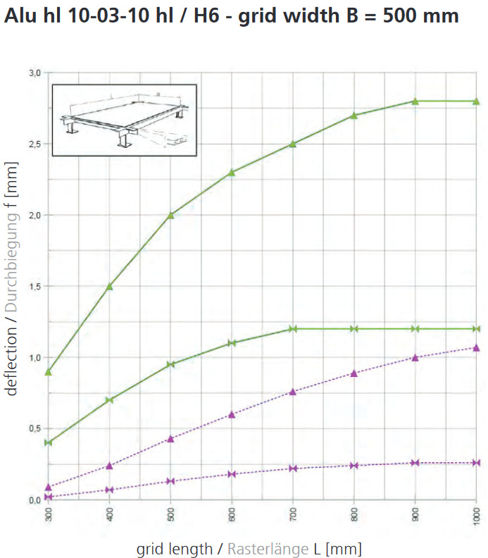
With carpet as floor covering the compressive strength of the stage floor depends solely on the floor panel. In view of the expected point loads (e.g. stiletto heels) the panel Metawell® Alu hl 10-03-10 hl / H6 should be used because of its better compressive strength. This Metawell® panel type in size 1500 mm x 3000 mm can cover nine grid fields. With a grid width of 500 mm the deflection diagram of Metawell® Alu hl 10-03-10 hl / H6 shows a deflection of about 1.1 mm for a surface load of 300 kg/m². Thanks to the supporting effect of the neighbouring panel fields the real deflection may be expected to be even lower.
Design example 2
Given conditions for a raised stage floor with carpet:
- Load: surface load 500 kg/m²
- Flooring: parquet (design free)
- Grid width: 750 x 750 mm
- Support width: 25 mm
- Deflection: < 1.5 mm
The floor‘s compressive strength is ensured by the parquet covering. That is why the panel type Metawell® Alu hl 10-03-10 hl / H11.5 can be used. The support performance of the rigidity of the parquet has been neglected for the calculation because of its rigidity – a mathematical statement would be extremely difficult – that means that the calculated design always contains some “safety“. Diagrams for a surface load of 500 kg/m² are not available, but thanks to the linear influence of the load the deflection can be projected with the factor 500/300. With a surface load of 300 kg/m², a grid width B of 750 mm and a grid length L of 750 mm the deflection diagram of Alu hl 10-03-10 hl / H11.5 shows a deflection of approx. 0.6 mm. Multiplied with the factor 500/300 the deflection to be expected is approx. 1.0 mm with a surface load of 500 kg/m². Thanks to the supporting effect of the neighbouring panel fields the real deflection may be expected to be even lower.
Deflection diagrams
The deflection diagrams attached hereafter are valid for “area loads of 300 kg/m²” and “point loads of 100 kg in the centre of the panel” for a panel that is supported on all four sides with a support width of 25 mm. The data may serve as guidelines only. It is strongly recommended to make tests subject to the individual application parameters, as the support conditions and floor coverings vary from application to application, which makes a merely mathematical assessment impossible. All particulars are given without obligation; errors and modifications are reserved.
Alu hl 10-03-10 hl / H6 – grid width B = 500 mm
Alu hl 10-03-10 hl / H11,5 – grid width B = 500 mm

Alu hl 10-03-10 hl / H6 – grid width B = 750 mm

Alu hl 10-03-10 hl / H11,5 – grid width B = 750 mm

Here you get back to the overview lightweight components for shipbuilding.
There you will find our shipbuilding brochure as a download, videos on our products, technical data sheets and more.
